THE COMMUNITY PORCH
ROLE | MODULAR CONSTRUCTION UNITS & PROGRAM LAYOUTS, RAINWATER HARVESTING SYSTEM, PLUMBING INTEGRATION SYSTEMS, LIGHTWELL INTEGRATION, 3D PRINTED MODEL & CALIBRATION
TEAM | MADILYN LAMBERT & ELIJAH HESS
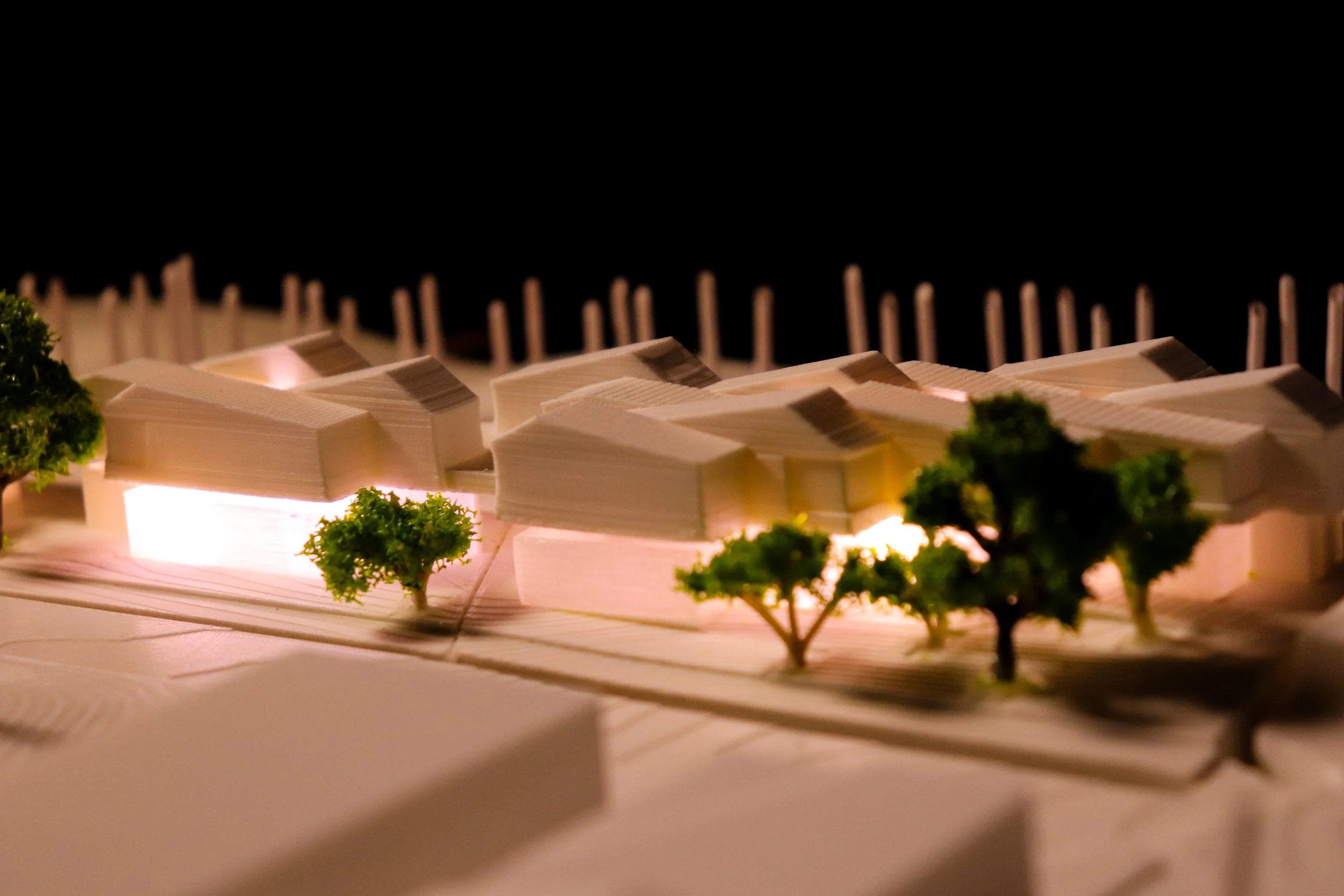
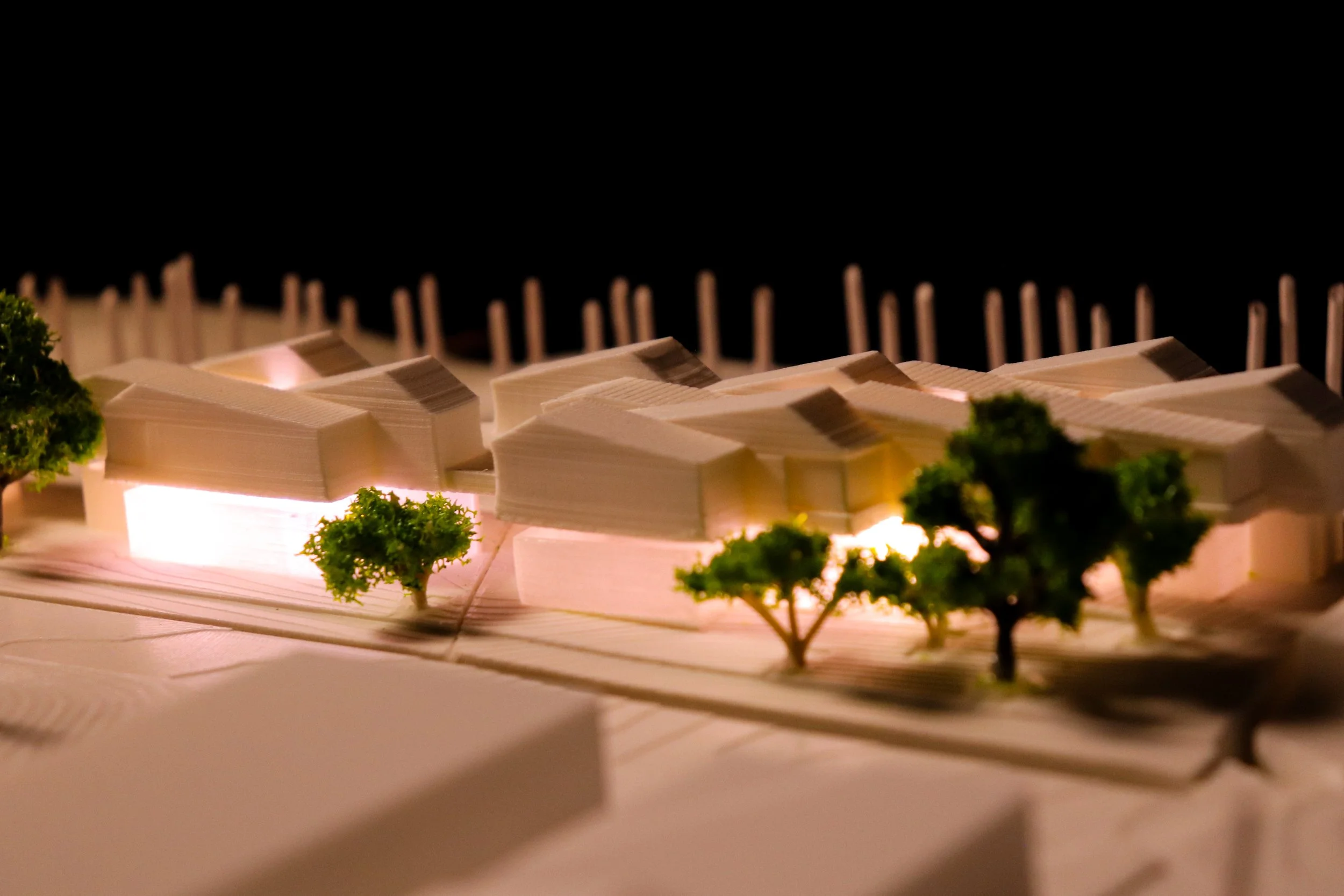
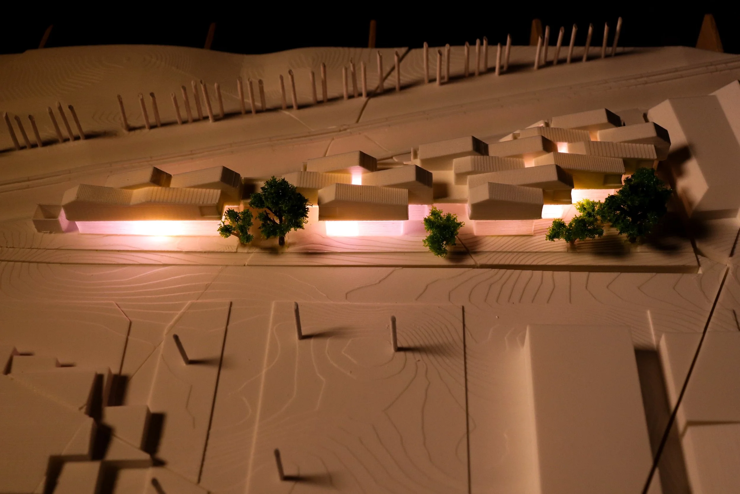
The Community Porch is a modular, climate-responsive development in Knoxville designed at the intersection of civic gathering and passive environmental performance. Conceived as both a neighborhood threshold and an ecological engine, the architecture uses sculpted roof geometries calibrated for stormwater harvesting, prevailing-wind ventilation, and optimized daylighting. Illuminated translucent storefronts activate the street level, while deep internal lightwells draw natural light inward, creating an adaptable, multi-material framework dedicated to community connection and environmental resilience.
MODULAR ZONING & ROOF FORMATION
LOCATION | HOMBERG DRIVE, KNOXVILLE, TN
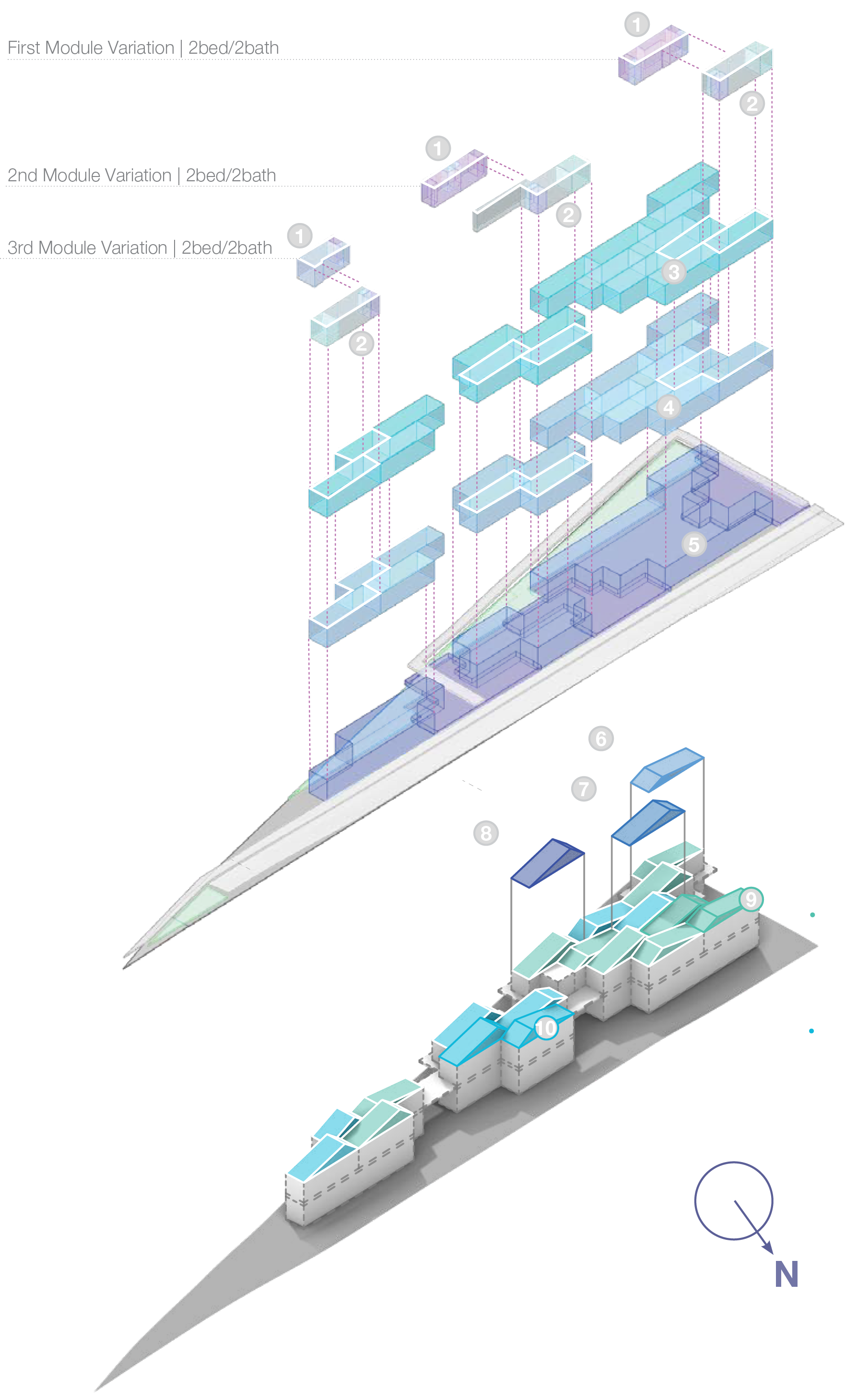
The second floor of the residential units features a layout built on a standardized modular framework. Prefabricated living and utility modules are stacked above an open-span commercial foundation that is constructed on-site. This design creates a clear spatial boundary between private living spaces and public areas.
MODULAR FABRICATION | PREFABRICATED ASSEMBLY, PLACEMENT, & PUBLIC-PRIVATE UNIT ZONING
1
2
Private Space
3
6
7
8
4
9
10
Modular Unit Apartment Suites
Ground Floor Commercial Space (Not Modular Construction)
Alignment
Contrast
Public Space
4’
8’
Modular Units Broken into Bedroom and Living Space Modules
6’
5
ROOF FORMS | ROOF PROFILE DISTRIBUTION
41 % offset of 14,400 gallons/week average
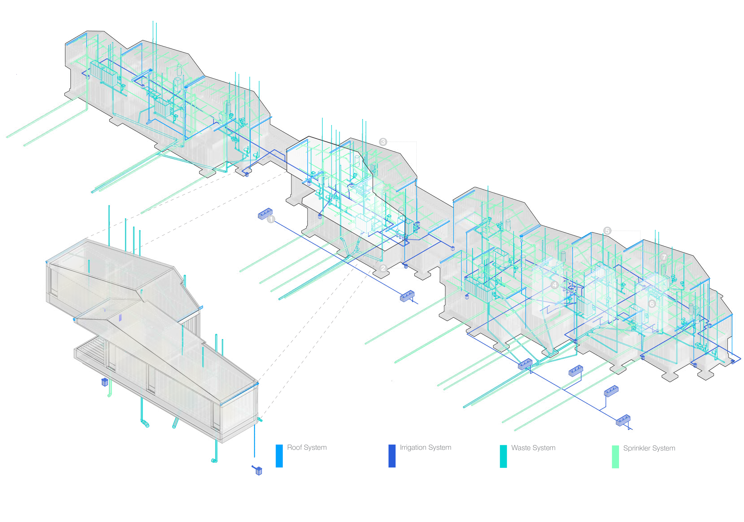
RAINWATER HARVESTING & PLUMBING INTEGRATION
1
2
Planter Box
0.98” per sq/ft greenspace is needed per/week, which = 0.623 gallons/sq/ft per week of water
Special Case: Planters need roughly 1.5 gallons of water per week
Total Planter sq/ft: 367 sq/ft for 6 planters
Total Other Greenspace = 7,393 sq/ft
1 Lightwell = 61.3 sq/ft : 4 Lightwells = 245.27 sq/ft
Roof Water Collection = 10,549.26 sq/ft
RAINWATER COLLECTION & IRRIGATION
Total water collection from roofs + lightwells = 10,550 + 245 = 10,795 sq/ft
Total Greenspace + Planter sq/ft = 7,760 sq/ft
IRRIGATION GREENSPACE & PLANTERS CALCULATION
Amount of water needed to irrigate each week:
Planters: 337 sq/ft x 1.5 gallons/week = 550.5 gallons/week
Other Greenspace: 7,393 sq/ft x 0.623 gallons/week = 4,605.8 gallons/week
Total gallons/week of water needed: 550.5 + 4,605.8 = 5,153.3 gallons/week
Amount of Usable Water Capture from Roofs + Lightwells (assuming 90% is usable):
10,795 sq/ft x 0.98” per/week x 0.623 gallons/week x 0.9 (usable water) = 5,935.5 gallons/week of water collected
Therefore, we can irrigate planters and greenspace every week with our rainwater irrigation system, and have 777.7 gallons/week extra.
3
4
5
Lightwell Drip Edge
Cistern
Rain Chain
Water Collection Drain
$1,898.19
PROJECTED ANNUAL UTILITY SAVINGS
WATER SAVINGS
Withoverhead spray sprinklers, the city would supply the 10,795 sq/ft of greenspace + planters with 14,400 gallons/week of water
Offset Calculation:
5,931 gallons/week / 14,400 gallons/week = 0.4119 = 41.2% water saved
Our greenspace + planters would use 58.8% of the 14,400 gallons supplied per week
MONETARY SAVINGS
For spaces using over 20,000 gallons of water per month, the city of Knoxville charges $6.15 per 1000 gallons of water
Monthly Savings:
(5,935.5 x $6.15) / 1,000 = $36.50 per/week of savings ($158.05 per/month)
Annual Savings:
$36.50 x 52 weeks = $1,898.19 per/year of savings
STORAGE
Underground Plastic Rainwater Tank
1 Tank holds 1,200 gallons of water
Building needs 5 x 1,200 gallon Rainwater Holding Tanks
Lightwell
40 Gallon Hot Water Heater
41%
TOTAL MUNICIPAL WATER OFFSET
14,400
Gallons/Week
KNOXVILLE RAINWATER PER/YR = 50-51”
CALCULATED STORMWATER CAPACITY CAPTURE
6
7
RESIDENTIAL
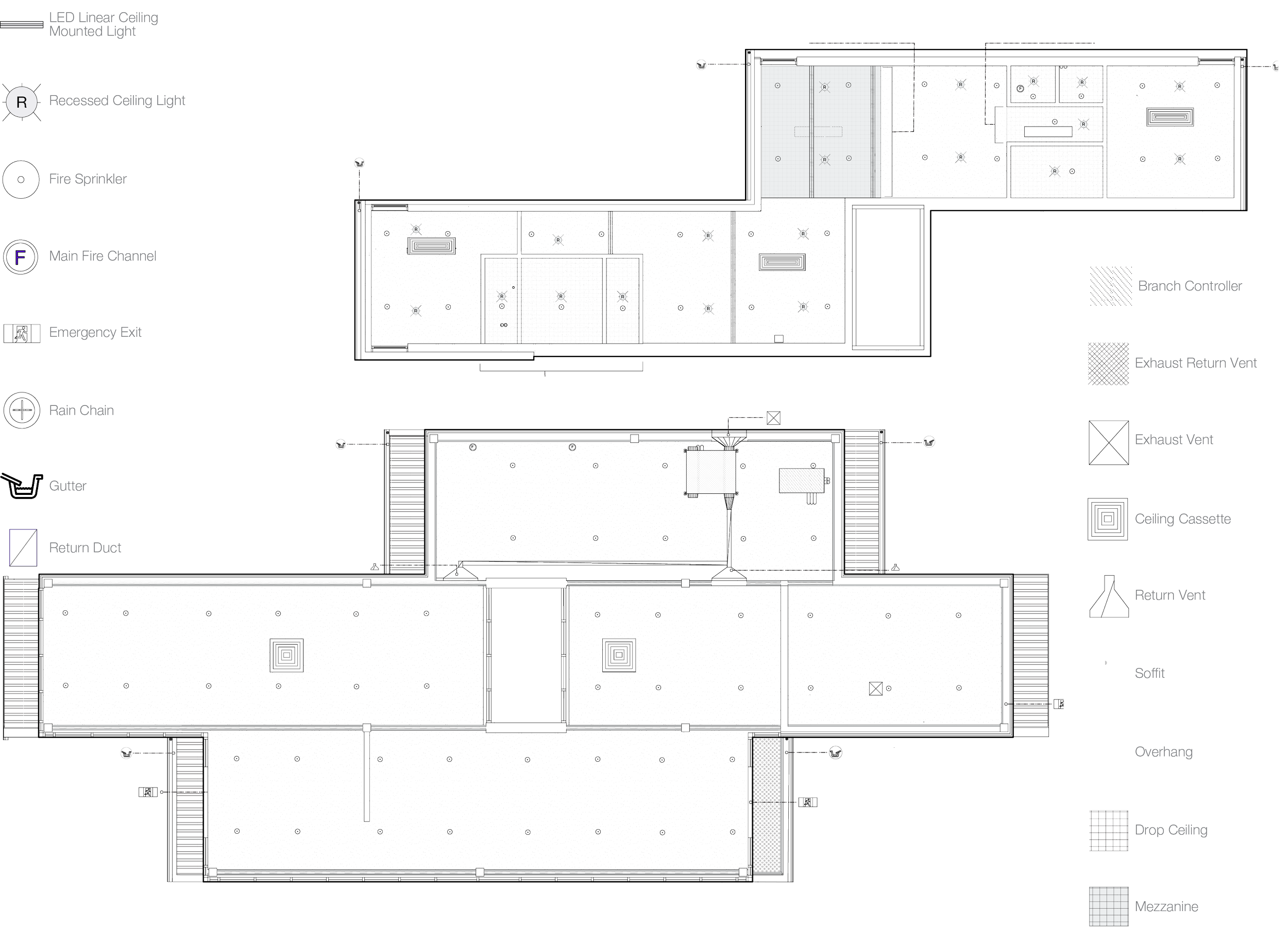
REFLECTED CEILING PLANS
1
2
Mezzanine: 5’ 8”
3
Drop Ceiling: 4’ 6”
Drop Ceiling: 2’ 3”
COMMERCIAL

RESIDENTIAL UNIT TYPE A
Square Footage: 1,250 sq/ft
Number of Residential Units: 1 Unit
Public-to-Private Opening Dimension: 31’
Module Dimensions: 40’ x 12’ x 8’
UNIT LAYOUT INTEGRATION & SPATIAL SYSTEMS COORDINATION
1
2
Exhaust Vent
Lightwell

RESIDENTIAL UNIT TYPE B
Square Footage: 913 sq/ft
Number of Residential Units: 2 Units
Public-to-Private Opening Dimension: 7.5’
Module Dimensions: 12’ x 40’ x 8’
3
4
Hot Water Heater Above
Exhaust Vent above Ceiling
6
5
Cassette
Washer/Dryer in Mechanical Closet
7
Mezzanine

RESIDENTIAL UNIT TYPE C
Square Footage: 889 sq/ft
Number of Residential Units: 1 Unit
Public-to-Private Opening Dimension: 7’
Module Dimensions: 12’ x 40’ x 8’ and 12’ x 27’ x 8’
ENVELOPE TECTONICS & THERMAL BOUNDARIES
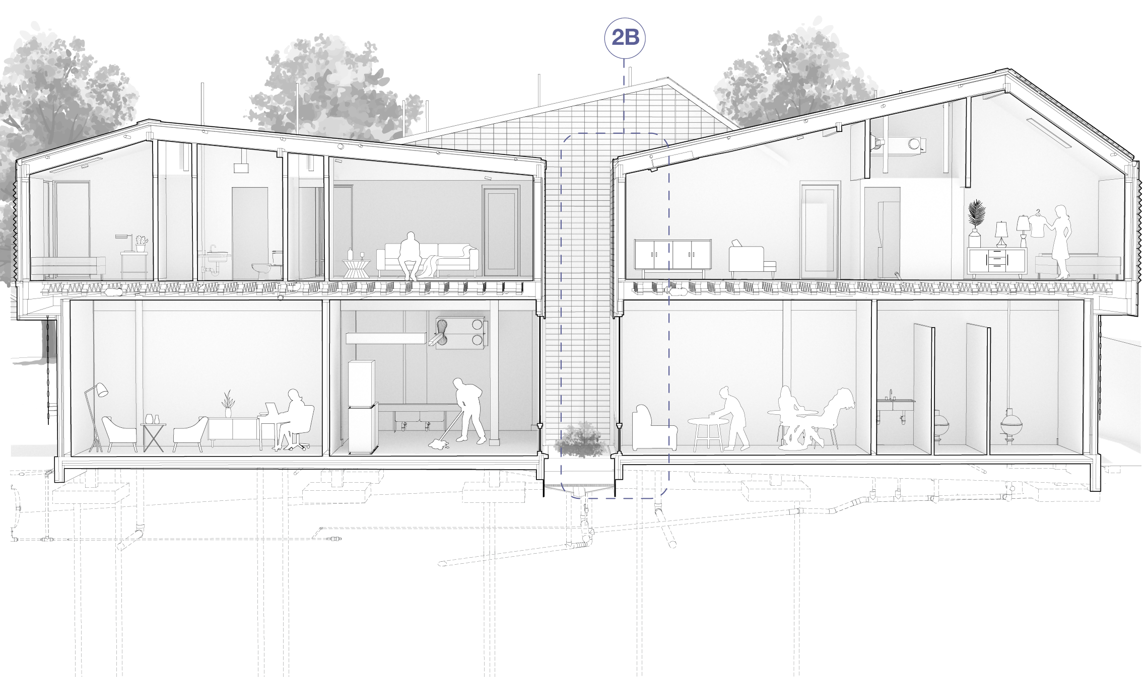
The perimeter enclosure is a high-performance assembly designed to reduce thermal bridging and support rain-collection pathways. To reduce conductive thermal short circuits and prevent interstitial wall condensation, a continuous exterior rigid insulation barrier encloses the structural framing assembly. The multi-layered exterior wall transitions from a Corten standing-seam roof (R-60.31) to a continuous terracotta rainscreen envelope (R-31.38), using integrated weather membranes and continuous air cavities to prevent moisture penetration. The central lightwell core features operable window tracks, creating a passive stack-ventilation system within the daylighting cavity. The system naturally transfers thermal loads from the lower commercial areas while directing roof runoff into subgrade site filtration cisterns via a drip-edge gutter system.
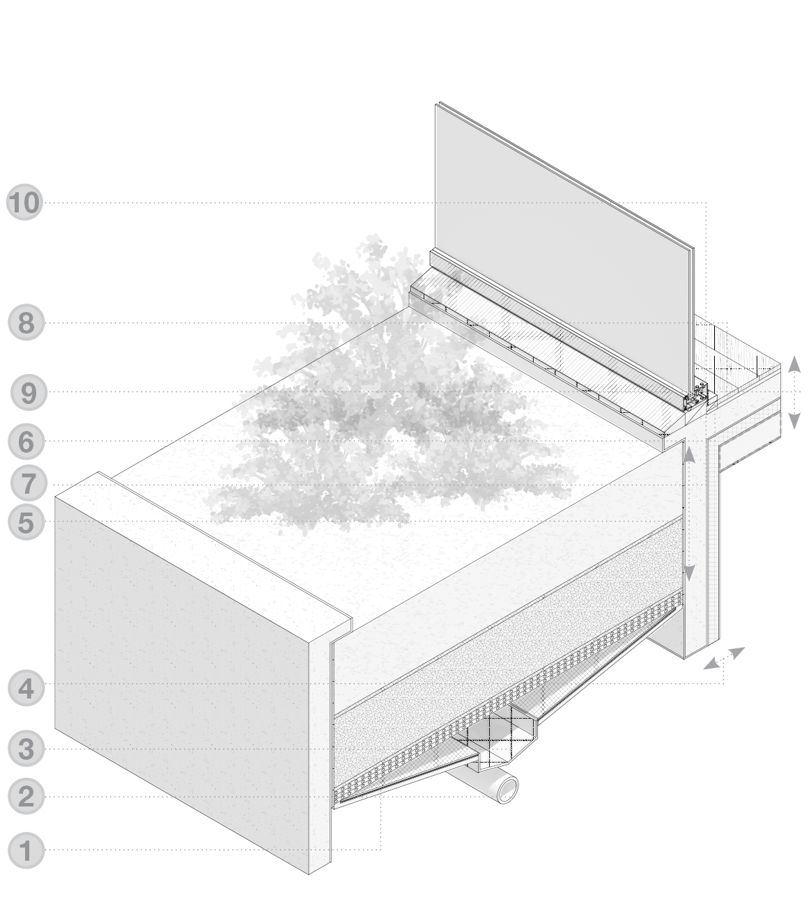
LIGHTWELL RAIN COLLECTION AT FOUNDATION
1
2
1/4” Geotextile Fabric
Weather Membrane
Metal Slope to Drainage System
2” Irrigation Pipe to Cistern
3
4
Rain Collection Sloped Channel Drain
1/4” Geotextile Fabric
Weather Membrane
4” Concrete Retaining Wall
2” Mineral Wool Rigid Insulation
Vapor Barrier
5
6
7
8
9
10
12” Soil Layer
1/4” Geotextile Fabric
12” Gravel Layer
1/4” Geotextile Fabric
Atlantis Flo Cell 0.79” (x3) - Neocell
Wood Blocking
Aluminum Sloped Parapet
Aluminum Mill
3/4” Hardwood Floor
3/4” Plywood
4” Concrete Retaining Wall
Weather Membrane
2” Mineral Wool Rigid Insulation
Vapor Barrier
Gravel
1/4” Geotextile Fabric
2250 IG Curtain Wall System Type “B” Screw Spline Assembly 4-1/2” System (1” & 1/4” Infill)
LIGHTWELL SECTION
1
2
3
4
5
6
ROOF ASSEMBLY - TOTAL R: 60.31
Corten Standing Seam Panel
2” Mineral Wool Rigid Insulation
Weather Membrane
1/4” Densglass Sheathing
12” Mineral Wool Batt Insulation
5/8” Gypsum Board
Roof Drip Edge
TERRACOTTA WALL ASSEMBLY - Total R: 31.38
Terracotta Rain Screen
Air Gap
1” Mineral Wool Rigid Insulation
Weather Membrane
5/8“ Densglass Sheathing
6” Mineral Wool Batt Insulation
5/8” Gypsum Board
Wood Truss
WINDOW ASSEMBLY - Total R: 1.61
Double Pane Glass
Skylight Ventilation Window
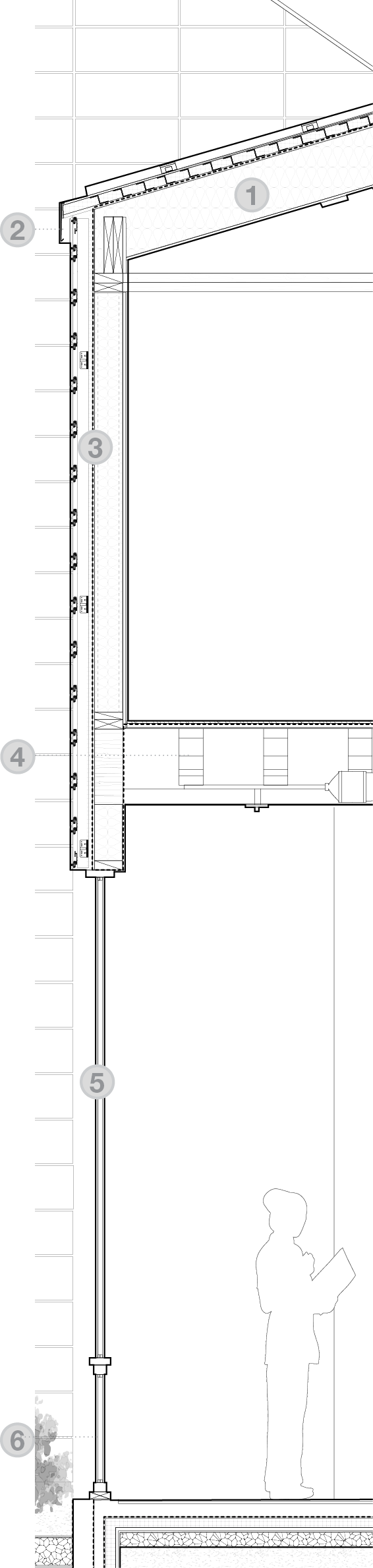
LIGHTWELL WALL SECTION - 2B
PHYSICAL FABRICATION & SPATIAL PROTOTYPING
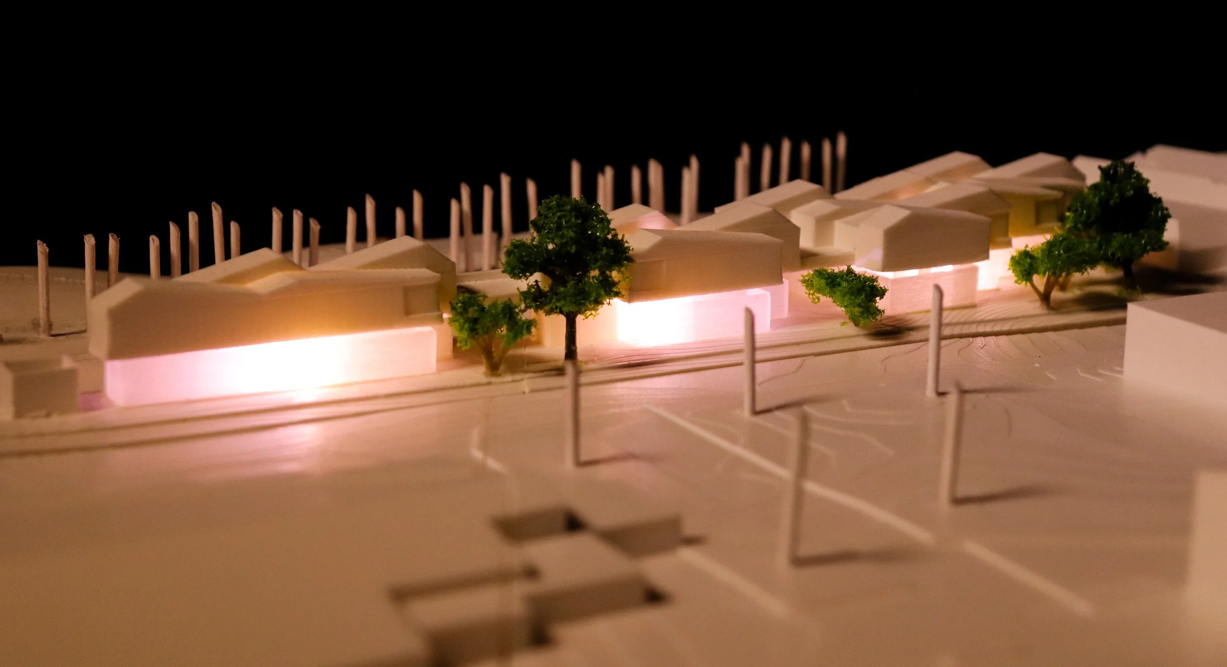
As a multi-material prototype, the physical 3D Model was created on an optimized Bambu Lab A1 Mini platform using calibrated parameters in Bambu Studio.
The structural components use a material pairing: dense PLA Matte outlines the opaque structural framing and perimeter envelope, while specialized Translucent PETG lets integrated internal lighting cavities diffuse light through the translucent commercial storefront and internal light wells.
FABRICATION METHODOLOGY & ADVANCED PRINT CALIBRATION
To troubleshoot warping, stringing, and overall model cleanliness, I tweaked advanced settings in Bambu Studio to finalize the 3D Model. During slicing, I adjusted retraction speed and distance, bed temperature calibration, seam position, infill and density, layer speeds, outer and inner wall speeds, and auxiliary cooling fan settings, along with other micro-performance tweaks. To ensure the final print's readability, we continuously tweaked advanced print settings and printed and analyzed several part iterations. The final assembly incorporates a custom-spliced LED wire harness embedded in the print, anchored by a series of flush-fit magnets that secure the residential upper floor while allowing seamless, non-destructive removal for section-cut evaluation.